A Day in the Life of a CAM Programmer Using DigitalCNC

CAM Said 1:05. The Machine Said 6:27.
How DigitalCNC caught a five-minute-per-pocket error on an unproven aluminium bulkhead rib, before any metal was cut.
A new STEP file drops into the folder. A large aluminium bulkhead rib — bespoke, with no past program data or cutting history to lean on. Somewhere in it sits a 60 mm-deep, thin-walled roughing pocket headed for a gantry mill with an 80 kW HSK-63 spindle rated to 30,000 rpm. Plenty of power, but torque falls away hard above 18,000 rpm, and that is the constraint that decides which roughing strategy is actually available to you.
When aluminium roughing fails on an HSK-63 spindle at high surface speeds, it rarely wears out the insert or end mill gently. Built-up edge packs the flutes, welds material back onto the cutter, and causes catastrophic cutter fracture. On a high-speed spindle cartridge, that fracture takes out the toolholder, workpiece, and spindle bearings in milliseconds.
On an unproven part, finding the fastest safe toolpath strategy normally requires air-cutting, riding the feed override knob, or burning a test billet. This is how that decision moved entirely off the shop floor and onto the desk during a single afternoon.
Defining Feedrate Efficiency
Before examining the numbers, one term needs defining – efficiency. When DigitalCNC measures efficiency, it calculates the percentage of cycle time spent at or above 80% of the programmed feedrate.
A low efficiency percentage points to a path where the CNC controller spends the cut decelerating: throttling back for high-density G-code points, managing corner look-ahead limits, or struggling with servo acceleration, never reaching the feedrate commanded in the CAM program.
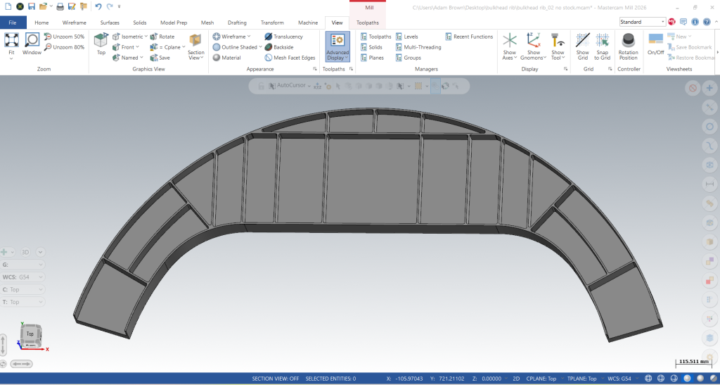
The part: a large aluminium bulkhead rib, with the 60 mm-deep thin-walled roughing pocket under review.
The Initial Toolpath Selection
The tooling data offered two viable strategies at similar theoretical metal removal rates (MRR):
- A three-flute traditional offset approach using low axial depth of cut (ap) and high radial engagement (ae).
- A four-flute dynamic trochoidal approach using low ae and full axial depth (ap) at a lower torque load.
The trochoidal option looked like the safer bet, and on tool life grounds it was: 2 mm radial engagement, no corner spikes, and none of the sudden torque demand that snaps a long-reach cutter in a 60 mm pocket.
The CAM cycle time estimate reinforced that choice. The dynamic path posted at 1:05 against 0:50 for the traditional offset area-mill path — a 15-second difference per pocket. On a high-RPM spindle and an unproven part, choosing the dynamic path was a sound engineering call based on the data available at the desk.
The Actual Machine Response
Running the posted G-code through a kinematic model of the specific machine (accounting for controller parameters such as look-ahead, acceleration/deceleration limits, and machining tolerance) fundamentally changed the output.
DigitalCNC calculated the actual run time for the dynamic path at 6:27 with an efficiency rating of 24%.
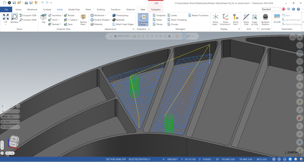
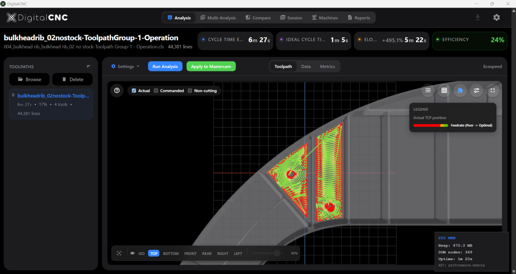
Kinematic analysis of the dynamic path. Red segments indicate where actual feedrate drops below 80% of programmed feed.
Point spacing on that trochoidal path averaged 0.4 mm. At a commanded feedrate of 6,000 mm/min, the CNC control must process 250 blocks per second. Look-ahead effects and kinematic constraints throttled the feedrate: the control could not process the point-dense stream and plan the direction changes within tolerance while still holding the commanded feed. The controller spent 76% of the motion cycle slowing down through the interpolated toolpath.
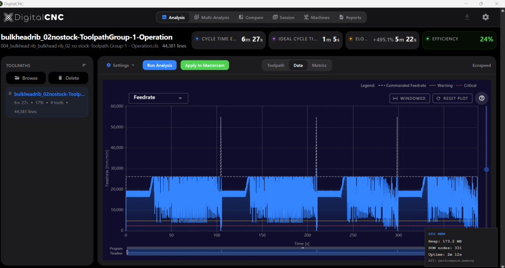
Feedrate (solid blue) plotted against commanded feed (dashed ceiling) over time.
CAM software assumes linear movement at full programmed feed. On complex point-dense paths, that assumption can introduce a 20–40% error window. In which case, block-processing bottlenecks can turn the conservative toolpath into the slowest option on the machine.
Optimisation Cycle
Using the kinematic model to re-simulate changes instantly on the programmers laptop allowed for targeted path adjustments before posting code to the floor:
- Ramp Geometry: Replacing the tight helical entry with a form ramp matching the pocket geometry maintained drive motion and reduced entry cycle time, bringing overall time from 6:27 down to 4:50.
- Post Processor Arcs: Analysing feed dips in the entry revealed the post processor was emitting tiny 3D linear segments instead of arc commands. Forcing true G02/G03 arc output cleaned up the execution stream, dropping time to 4:41.
- Control Tolerance: Opening the high-speed machining tolerance from 25 µm to 60 µm on this roughing operation allowed the look-ahead algorithm to smooth vector transitions, bringing time down to 4:19.
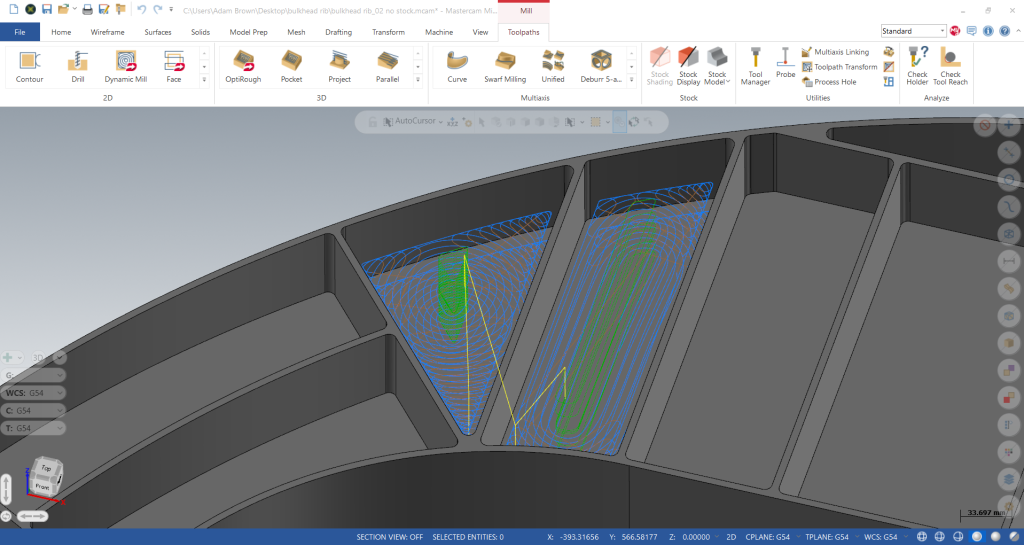
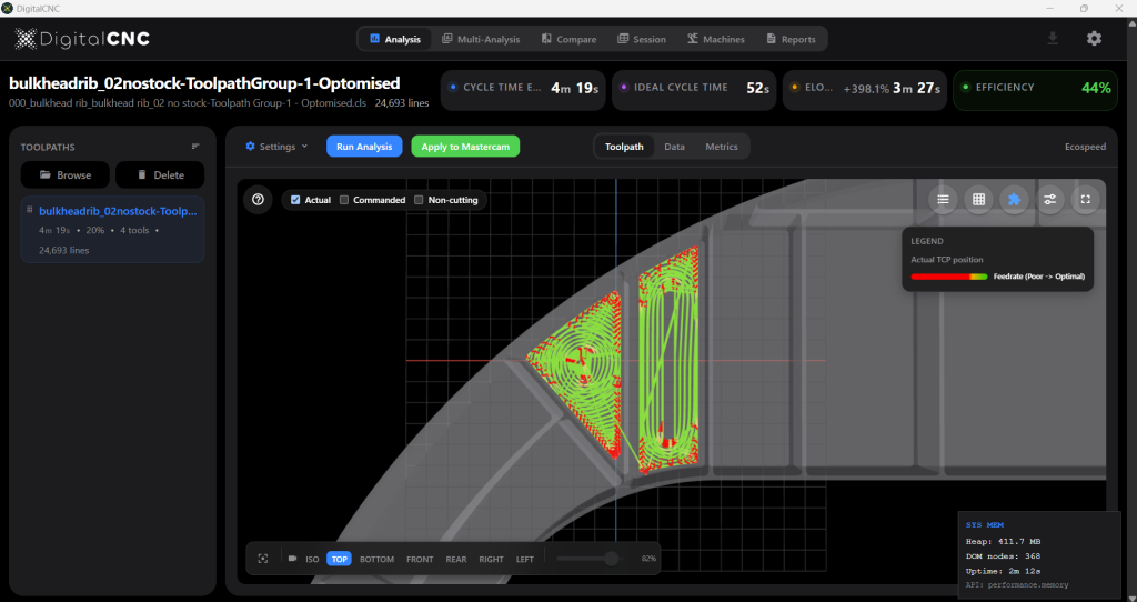
Re-simulated dynamic strategy following ramp geometry, arc output, and tolerance changes.
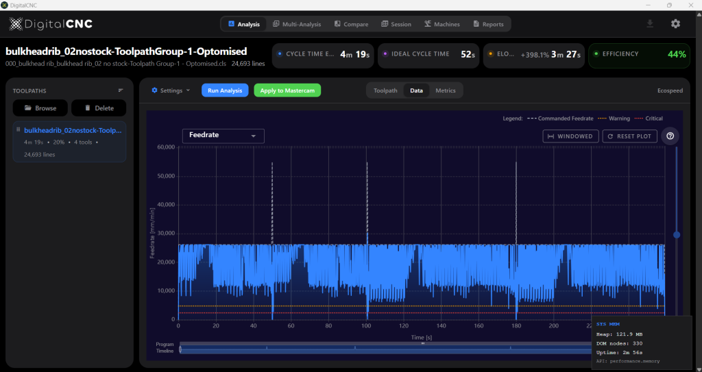
Feedrate plot with dynamic strategy following ramp geometry, arc output, and tolerance changes.
These three edits saved 2 minutes and 8 seconds on a single pocket. Across a structural rib with dozens of internal cavities, that minor adjustment scales rapidly: turning minutes into hours of recovered machine time on every part, and compound savings into hundreds of thousands of pounds across the entire programme.
Analysing the Offset Path
The traditional offset path presented a different constraint. Out of the box, it posted at an actual execution time of 1:31 at 42% efficiency. However, the feedrate and chip load analysis highlighted a severe mechanical risk.
At internal corners, maximum chip thickness dropped under 12 µm, below the edge radius of the cutter. At that point, the tool stops shearing metal and starts ploughing, creating extreme friction, and likely induced chatter right before the tool engages the heavy radial wedge in the corner.
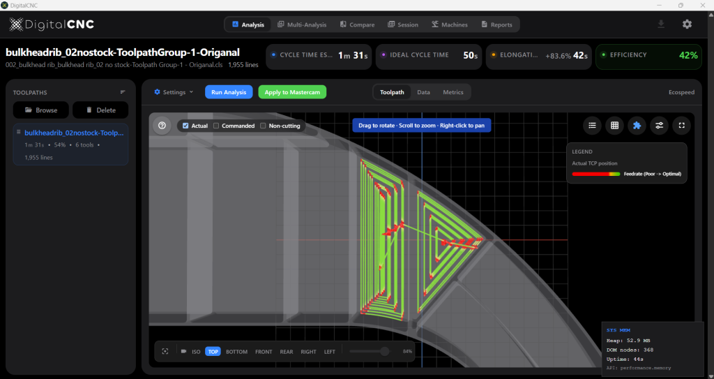
Original offset toolpath showing chip thickness collapse at sharp directional turns.
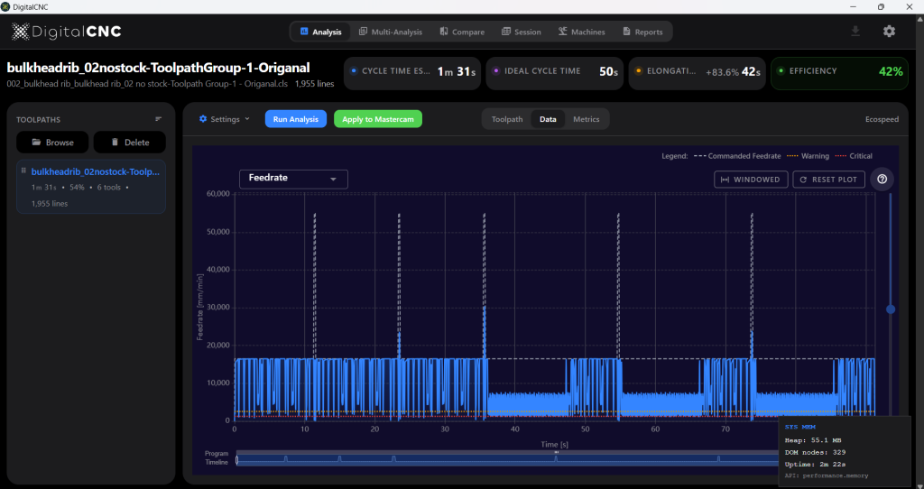
Feedrate plot showing feedrate collapse at sharp directional turns
The toolpath was corrected through CAM parameters:
- High-speed profile and offset tolerances to round the corners, balancing rounding against stock left for the next operation (dialled from a deviation tolerance value of 5 down to 3). Note that even though an extra lap was addeedaround the pocket, the cycle time is still maintained due to the improved acceleration performance (1:26 over the original 1:31).
- Arc-fit rounding on the linking (out-of-cut) moves, killing the right-angle repositions that jar the guideways and leave dwells.
- Platform tolerance opened to 60 µm.
Efficiency improved from 42% to 80%. Total run time changed negligibly (1:31 to 1:33) despite adding corner-rounding motion loops. Crucially, chip load was maintained above the 15 µm minimum threshold throughout the entire cutting pass, eliminating the rubbing action that leads to edge breakdown.
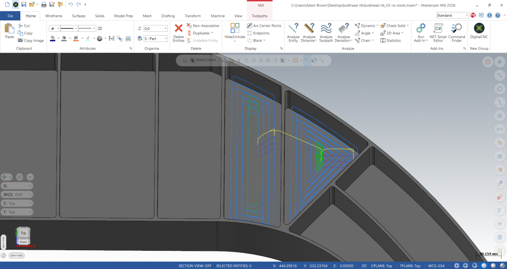
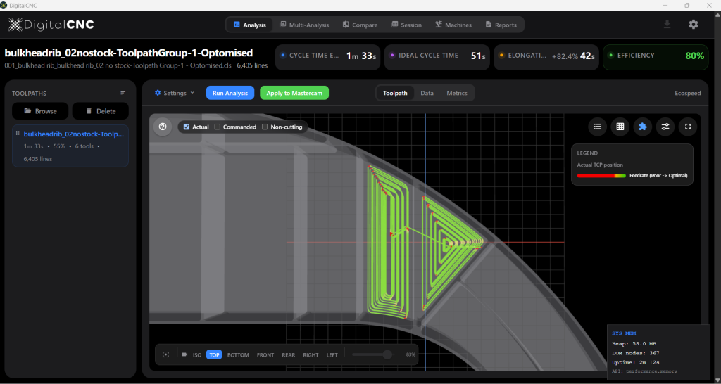
Corrected offset path with continuous corner radii and sustained minimum chip thickness.
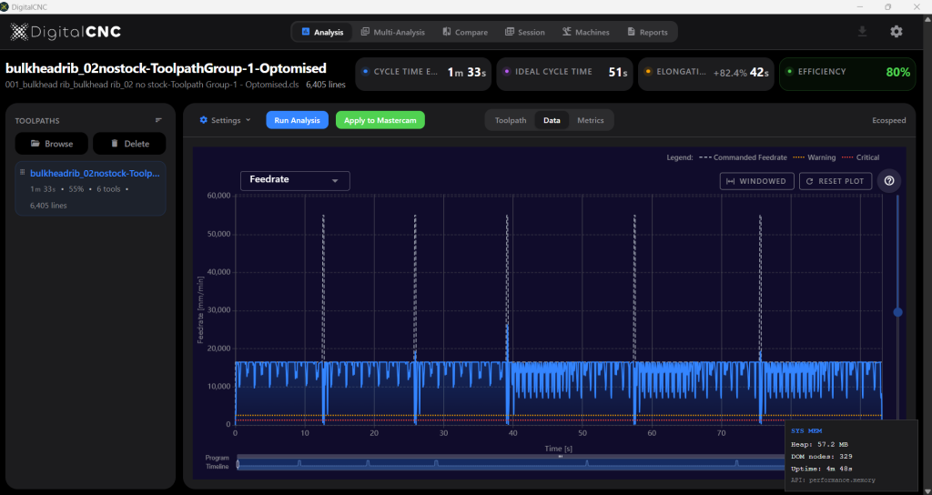
Feedrate plot with corrected offset path, continuous corner radii and sustained minimum chip thickness.
Comparing the Unmodified Paths
The baseline CAM estimates placed the dynamic path at 1:05 and the offset path at 0:50 — a 15-second delta.
When run through the machine controller physics model, the actual times were 6:27 for dynamic and 1:31 for offset. The engineering rationale behind choosing dynamic was sound, but the CAM software lacked visibility into controller limits. The real-world difference between those choices was nearly five minutes per pocket.
Full Component Results
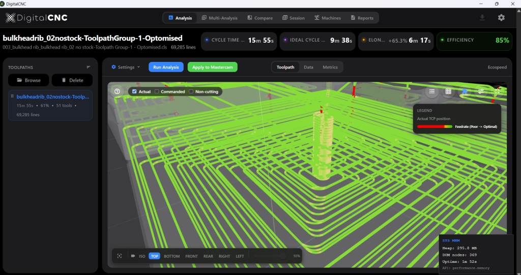
Applying these verified path strategies across the complete bulkhead program brought the overall machining efficiency to 85%. No air-cuts were performed, no test scrap was produced, and no tooling was lost evaluating corner loads.
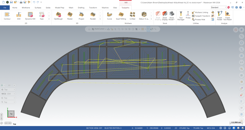
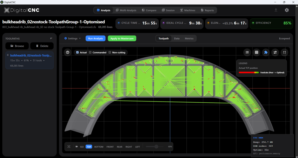
Complete bulkhead rib toolpath optimised to 85% overall machine efficiency.
What the Estimate Could Not See
Nothing in the original decision was wrong. Two strategies, similar theoretical MRR, one with clearly better tool life at 2 mm radial engagement in a 60 mm pocket. Every input available at the desk pointed at the trochoidal path.
What was missing was the machine. A CAM estimate is geometry divided by feedrate. It has no view of block throughput, look-ahead depth, drive acceleration, or the tolerance band the control is actually working to. On a point-dense path those omissions are not a rounding error. They inverted the answer.
Two strategies. One CAM cycle time reading fifteen seconds apart. Nearly five minutes apart on the machine. The whole call turned on a gap no CAM estimate could show, and it was closed in five clicks before anything reached the floor. No billet, no override knob, no afternoon of nerves.
That is one pocket. This rib has dozens.
The question is no longer which strategy looks fastest. It is whether the machine agrees.