Look-Ahead: The Controller Function Deciding Your Feed Rate Before You Do
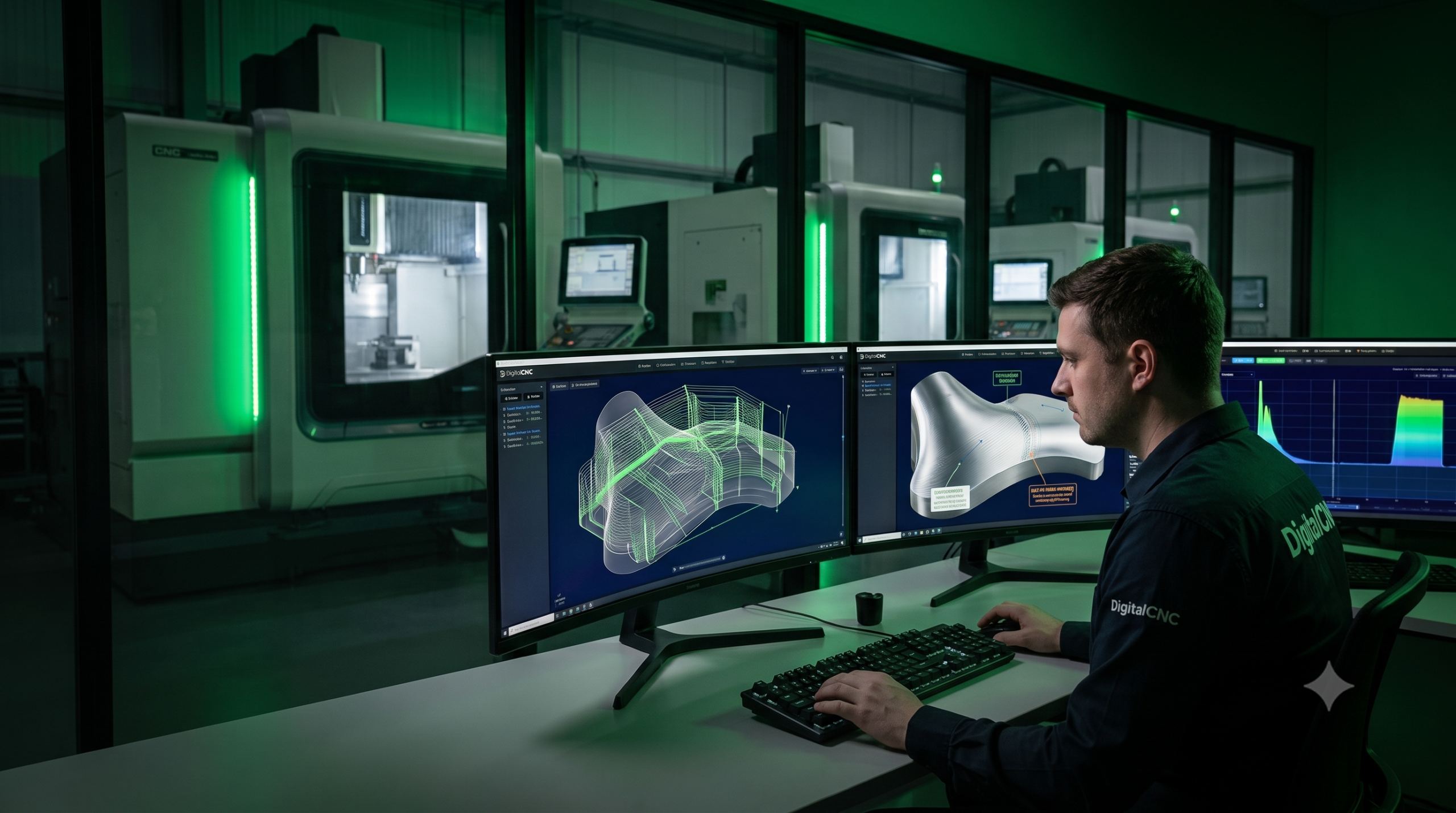
Most CNC operators have seen it happen. The program says one feed rate, and the machine runs something else.
You are watching the feed display through a finishing pass. The code looks fine, the programmed feed is steady, and the toolpath is clean. Then, as the cutter moves through a tight area, across a freeform surface, or into a region with lots of small direction changes, the machine quietly backs off. No alarm, no obvious mistake, no dramatic event. Just a feed rate that refuses to hold.
That behaviour is not random, and it is not the machine being cautious in some vague way. It is the controller doing one of its most important jobs: looking ahead in the program and deciding how fast the machine can actually move without exceeding its physical limits. That function is called look-ahead.
What the Controller Knows That CAM Does Not
CAM creates a toolpath from geometry. It outputs positions and feed rates, and in the program those feed rates can look simple: move from here to here at this speed. The machine has a harder job.
Every axis has mass. The table, spindle, head, rotary axes, ballscrews, motors and driven components cannot change speed or direction instantly. Any change in direction demands acceleration, and any fast change in acceleration creates jerk. Both are limited by the drives, the machine structure and the parameters set by the machine builder.
So while CAM may output a feed rate, the controller has to ask a different question: can the machine physically reach and maintain that feed rate through the motion that is coming next? That is why the programmed feed rate is not a promise. It is a limit. The controller can run up to that value where the motion allows it, but it will slow down where the geometry, axis limits or smoothing settings require it.
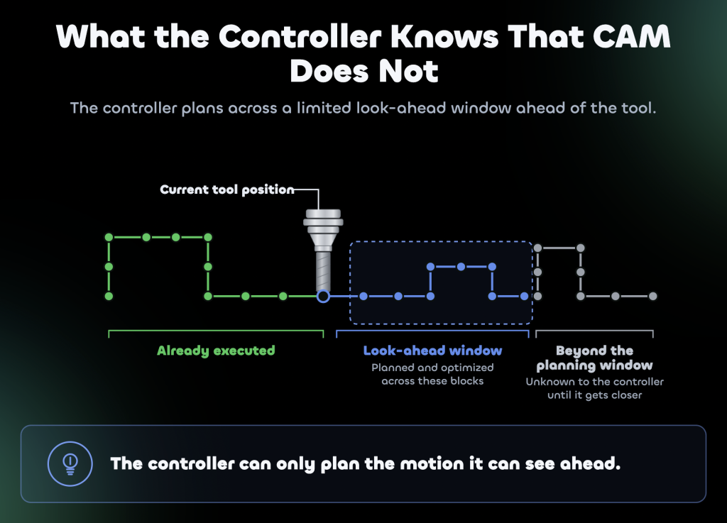
Look-ahead is the function that makes this possible. Instead of reading one line of code, moving, then reacting to the next line, the controller reads ahead through upcoming blocks. It studies the next section of motion and calculates a velocity profile that keeps the machine inside its acceleration and jerk limits.
Without look-ahead, the controller would have to treat every block transition as a possible stop. That would make complex finishing painfully slow and often unusable. With look-ahead, the controller can blend motion, maintain smoother feed and avoid unnecessary stopping. But there is a catch: the controller can only plan what it can see.
When the Toolpath Outruns the Planner
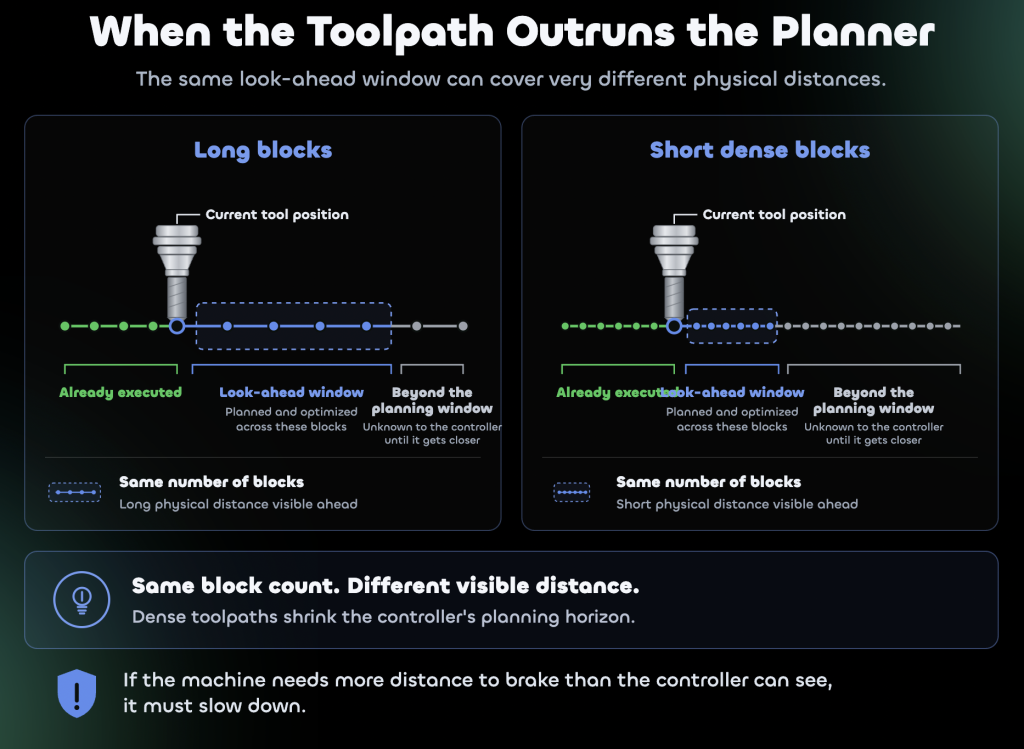
The controller’s look-ahead window is finite. It can only plan across the blocks it has read, stored and processed. If the program is made of long, simple moves, each block covers a useful amount of physical distance and the controller can see a reasonable distance ahead of the tool.
But finishing programs are often not like that. On freeform surfaces, especially in aerospace work, the toolpath may be made from thousands of tiny linear moves. Each line of code may cover only a very short distance. The controller may still be looking ahead the same number of blocks, but those blocks now represent a much shorter distance on the part.
That matters because the machine needs distance to slow down. If the controller cannot see far enough ahead to know what is coming, it cannot safely commit to a high feed rate. It has to protect the machine, the part and the process. So it slows down. The controller never commits to a speed it cannot safely brake from within the distance it can see. That single planning rule explains most of the feed behaviour this article describes.
This is one reason two programs that look almost identical in CAM can behave differently on the machine. The same surface might be posted twice with different point tolerances. Both programs may be geometrically close enough to look acceptable, but one contains many more short moves than the other. To the operator, the difference shows up as machine behaviour. One program flows. The other hesitates, pulses or sits below the commanded feed in complex areas. The geometry may be nearly the same. The block density is not. The controller feels the difference immediately.
This becomes more obvious in simultaneous five-axis work. Every block can contain rotary axis positions as well as X, Y and Z positions, so the controller is not only planning where the tool tip goes; it is also planning how the rotary axes move to keep the tool at the required orientation.
Rotary axes are often the limiting factor. A small change in tool angle at the cutter can require a much larger rotary move at the machine. When that happens over a short linear distance, the controller may reduce the feed rate even though the linear axes seem capable of going faster. That is why five-axis finishing can show feed drops earlier and more often than similar-looking three-axis work.
The symptom is familiar: the feed rate holds below programmed feed through complex regions, cycle time runs longer than expected, and there is nothing obvious in the G-code that explains why. The explanation is usually not one line of bad code. It is the controller managing dense geometry, limited look-ahead distance and machine dynamics.
Why the Same Program Behaves Differently on Different Machines
Look-ahead is not identical from one controller to another. The G-code may travel from machine to machine, but the way it is executed does not. Every controller family has its own way of reading ahead, smoothing motion, applying tolerance and calculating velocity through direction changes. That is why a proven program on one machine is not automatically proven on another.
For example, Heidenhain, Siemens and Fanuc controllers all have functions that help manage high-speed contouring and smoothing, but they do not all work in the same way. On a Heidenhain TNC640, CYCL DEF 32 TOLERANCE allows the controller to deviate within a defined tolerance to produce smoother and faster motion. On a Siemens 840D, functions such as G642 and the compressor functions perform a comparable role by smoothing block transitions and handling sequences of short linear moves within a tolerance band. On Fanuc controls, AICC provides high-speed contour control capability for smoother execution of complex paths.
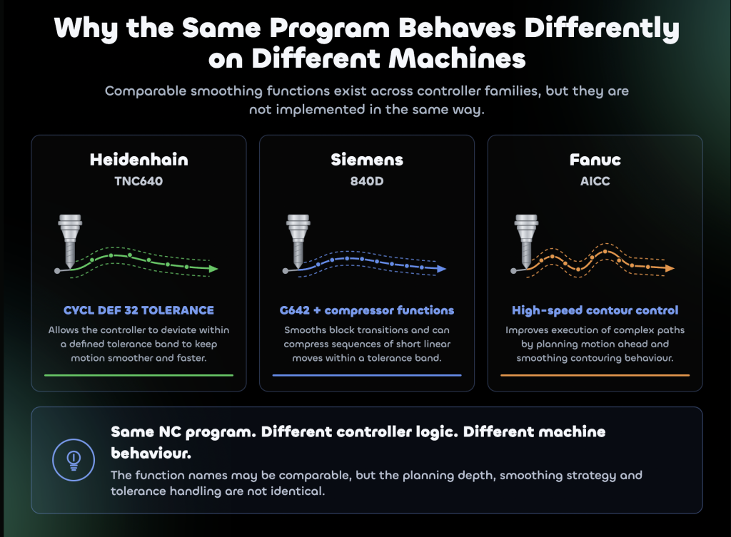
To an operator, these may all look like smoothing or high-speed mode. But they are not the same feature with different names. They use different planning strategies, they treat tolerance differently, and they can produce different feed rates, different acceleration behaviour and different surface results from the same NC program.
This matters in any facility where work moves between machines for capacity reasons. A job may be shifted from one machine to another because the spindle is free, the envelope fits, or the schedule demands it. The program loads, the setup is correct, the tool is right. But the machine does not move the same way.
The part may still be good. Or it may show new witness marks. Cycle time may change, tool wear may change, and the operator may have to adjust feed override, smoothing settings or prove-out strategy because the transferred process is no longer the same process. The program moved. The behaviour did not come with it.
How Feed Drops Become Surface Problems
A feed drop is not just a number on the screen. When the machine slows down but spindle speed stays the same, the feed per tooth falls. At first, that may sound harmless: slower feed, safer cut. But cutting tools do not work that simply.
A cutting edge needs enough chip load to shear material cleanly. If feed per tooth becomes too low, the edge can start rubbing or ploughing instead of cutting properly. That changes heat, pressure and surface condition at the tool edge. The edge is no longer forming a chip; it is pressing and smearing material below the level where clean shearing can begin.
In materials that work harden, this can become a bigger problem. The tool rubs or ploughs through one section, leaving the next part of the cut in a worse condition. The following pass then has to cut material that has already been affected.
This is how controller behaviour can turn into inspection findings. The operator may see local finish changes around tight direction changes, witness marks where the tool spent longer in contact with the surface, polishing or rubbing marks in areas where the programmed feed looked fine, tool wear that does not match the expected cutting data, and cycle time that keeps drifting away from the CAM estimate as surface complexity increases.
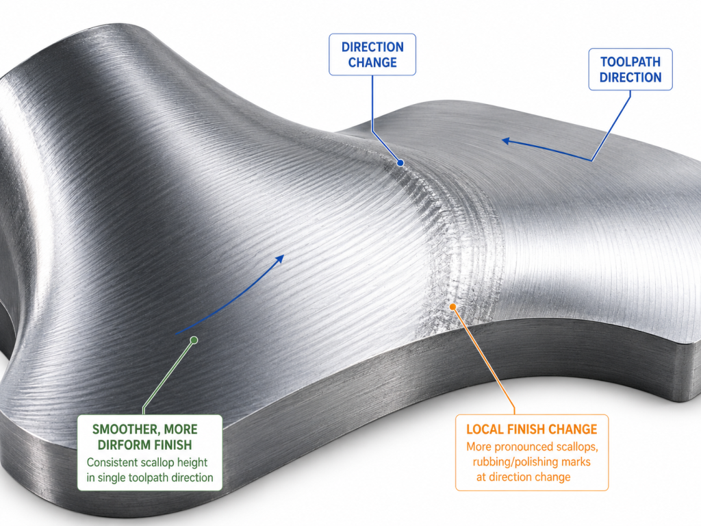
These problems can feel mysterious because the program does not show an obvious feed change. The CAM setup may look right, the tool list may be right and the setup sheet may be right. But the machine did not cut the surface at the feed rate everyone assumed.
The important point is that these areas are usually repeatable. The machine slows in the same places every time, because those locations are determined by the toolpath, block density, controller settings and machine kinematics. That means the problem is not random. It is predictable, but only if the execution behaviour is visible before the job reaches the machine.
The Usual Workarounds, and Why They Only Go So Far
Experienced operators and programmers already work around this. They loosen point tolerance to reduce the number of tiny moves. They reduce feed rates in complex areas so the difference between programmed and actual feed is smaller. They use arc fitting or smoothing at the post to give the controller cleaner geometry. They run proving cuts to find out where the machine hesitates, marks or behaves differently from the CAM estimate.
These are all rational decisions. Nobody doing real production work waits for perfect theory while a machine is burning hours. If a surface is risky, people do what works. But each workaround has a limit.
Loosening tolerance can reduce block density, but it also changes the relationship between the toolpath and the intended form, and that trade-off depends on the part, the controller and the machine. Lowering the programmed feed can make the process more stable, but it often gives away cycle time across a whole region when the real problem only exists in certain areas. Post-side smoothing can help the controller process the path more efficiently, but it still does not show the operator or programmer exactly what the machine will do with that smoothed path. Proving cuts work, but they use machine time, material, tooling and inspection effort to discover behaviour that was already built into the combination of program, controller and machine.
That is the real issue. Most workarounds compensate for controller behaviour without making that behaviour visible. They reduce risk, but they do not fully explain the process.
How Programs Should Be Evaluated
A toolpath checked only as geometry is only half checked. The machine does not cut geometry alone. It cuts geometry through a controller, through drives, through axis limits, through smoothing settings, through rotary motion, and through the physical limits of the machine structure. That means cycle time estimates, feed rate assumptions and surface finish expectations all depend on controller execution. If that execution is not visible, then the estimate is partly an assumption.
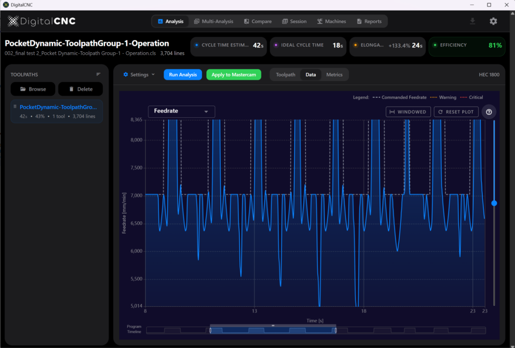
This gap between programmed intent and controller execution is the problem we work on at DigitalCNC: modelling how a specific machine and controller will execute an NC program before it runs. The output is the kinematic picture operators and programmers usually only get after the part has already been cut, including the feed rate the machine will actually achieve at each point on the toolpath.
Because if you have ever loosened a tolerance, lowered a feed across a surface you did not quite trust, adjusted smoothing, watched the feed display through a finishing pass, or run a proving cut just to find out where the machine would slow down, you were dealing with look-ahead. You were compensating for a controller decision you could not see.
The NC program was never the whole story. The real question is what the controller does with it.